
D I S C L A I M E R !
Due to rapid changes made in regards to COVID 19, all physical testing of the electrical subsystem is put on hold indefinitely.
Test Configurations since 4.5.2020
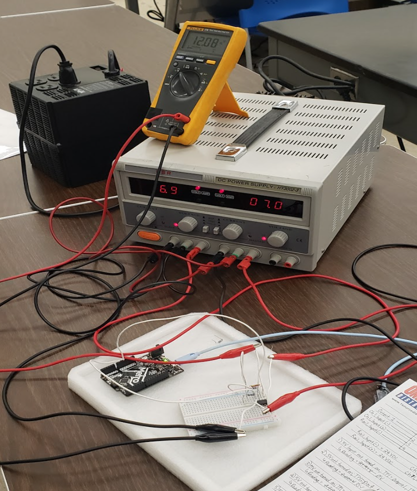
Below displays the physical set up for the electrical distribution box.

The electrical set up will undergo several tests to verify/validate the consistency of voltage measurements from different wall outlets in various locations set in Leeward Community College and University of Hawaii at Manoa. Below is a table that summarizes the current testing status of the electrical subsystem.
C confirmed that the tests have been executed, while NC signifies the tests’ incompleteness.
All tests have been completed in LCC, however, tests still need to be made in University of Hawaii.
| ID #: | Description: | C/NC |
| T1 | Validate supply voltage/current to devices | C |
| T2 | Verify supply voltage from outlet | NC |
| T3 | Verify supply voltage to Ardbox 20 | NC |
| T4 | Verify supply voltage to Allen Bradley 1606-XLP | NC |
| T5 | Verify supply voltage to Sola SCP30D524-DN | NC |
| T6 | Verify supply voltage to Kelly Pneumatic Digital Mass Flow Sensor | NC |
| T7 | Verify supply voltage to PX2AN1XX250PAAAXX | NC |
| T8 | Verify supply voltage to Prosense Digital Pressure Transducer | NC |
| T9 | Verify voltage supply to OP Amp, LM358P | NC |
| T10 | Validate integrity of test bench while in transportation | NC |
Experimental Tests and Test Results
Test 2 (T2): Wall Outlet Voltage

Test 3 (T3): Ardbox 20 Relay HF Incoming 24 VDC

Test 4 (T4.I) – Allen Bradley 120 VAC

Test 4 (T4.O) – Allen Bradley 24 VDC

Test 5 (T5.I) – SOLA 120 VAC

Test 5 (T5.O.24V) – SOLA 24 VDC

Test 5 (T5.O.5V) – SOLA 5 VDC

Test 7 (T7) – PX2 5 VDC

Test 8 (T8a-c) – PDPT 24 VDC

Testing Parameters for LM358P Op Amp
AC power from a standard US wall outlet is converted to usable DC voltage through an Allen Bradley (AB) 1606-XLP50 which is capable of supplying 24 VDC and a SOLA SCP30D524-DN which is capable of supplying 24VDC and 5VDC simultaneously. The use of a summation op amp is critical to pulling the transducer/sensor into the range allowed by the microcontroller and requires a reference voltage. Thus, the voltage regulator will be placed on the AB power supply.
Test 9 (T9) – Verify voltage supply to OP Amp, LM358P

| Rail Voltage | 24 VDC |
| Testing Input (1 Voltage) | 7 – 12 VDC (Second output to Power Supply |
| Input Resistance = 390 Ω | |
| Testing Input 2 Voltage | 5 VDC (Arduino Pin) |
| Input Resistance – 390 Ω | |
| Gain | 1 (voltage follower |
| Gain Settin Resistors = 490 Ω |
Results for LM358P Op Amp Testings:
| Reference | Sensor | Output of OP Amp | Units |
| 7.0 +/- 0.1 | 5 | 12.11 | V |
| 8.0 +/- 0.1 | 5 | 13.14 | V |
| 9.0 +/- 0.1 | 5 | 14.11 | V |
| 10.0 +/- 0.1 | 5 | 15.03 | V |
| 11.0 +/- 0.1 | 5 | 16.03 | V |
| 12.0 +/- 0.1 | 5 | 17.05 | V |
Integrity of Test Bench
Test 10 (T10) – Validate integrity of test bench while in transportation
** this test will be put on hold indefinitely due to quarantine.