
D I S C L A I M E R !
Due to rapid changes made in regards to COVID 19, all manufacturing of the mechanical subsystem is put on hold indefinitely.
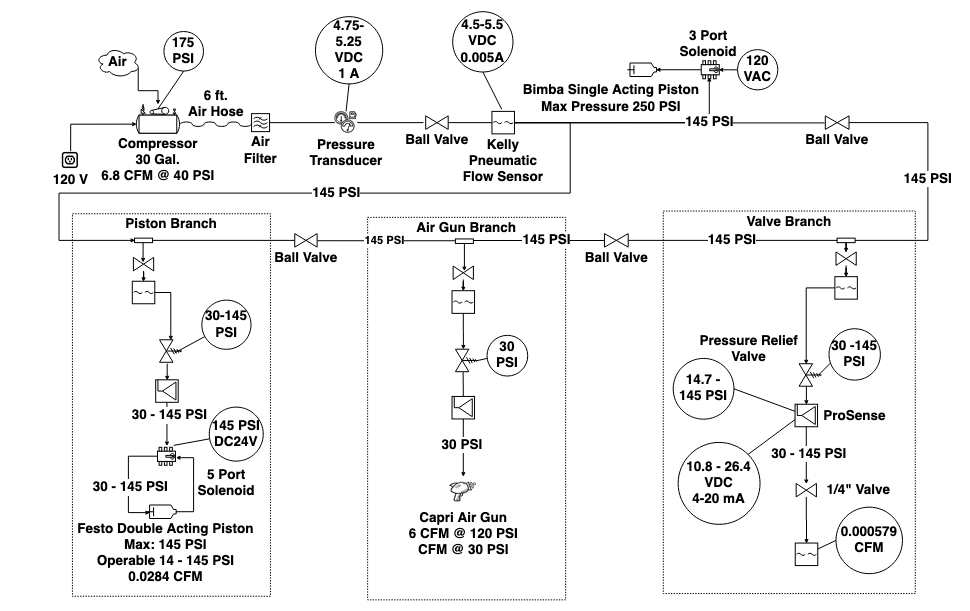
The main responsibility of a mechanical lead is to design the general layout of a pneumatic distribution system using mechanical components that will best execute the requirements of the system. This includes formulating a list of potential devices: air compressor, end user devices, and piping. To ensure that the best iteration of the pneumatic system is designed, potential mechanical components are narrowed down through trade studies. The air compressor and end user devices were categorized by the items’ air volume output (CFM), pressure output (PSI), cost, and availability. The type of piping was decided by its material, max pressure rating (PSI), dimension, availability, safety, and cost.
PERFORMANCE STATUS & TOP LEVEL REQUIREMENTS
| ANSI/ISA Tag | Requirements | Status |
| MR | The system will provide 10-15% over the maximum pressure required of the end user devices. | In Progress |
| IS5 9.1 | System will not exceed the air tank’s maximum pressure of 175 psi. | In Progress |
| MR | System will be able to supply the required maximum pressure and air volume of the end user devices (max pressure of device at 145 psi and max air volume at 6 CFM). | In Progress |
Click here for a complete list of standards of interest to the mechanical subsystem of the IIAPS project.
MECHANICAL P&ID
Click here for tentative MECHANICAL FINAL DESIGN CONCEPT (as of 3.30.2020)
Click here for pipe support analysis (as of 4.5.2020)
Click here for previous system layouts and general mechanical design concepts for air source and pipe distribution.
Click here for mechanical trade studies.