
Modifications to Programming Logic
The data from the pressure and flow sensors are received through 2 different parts of the ARDBOX 20; the I2C bus and the analog/digital pins. The first source of data is sent through the I2C bus are exclusively from the digital mass flow sensors (DMFS). The information from the sensors are sent as messages which contain various conditions and frames. In theory, the message should include a start condition, address frame, reading or writing bit, acknowledgement bits, data frames, and a stop condition as shown in the figure below.
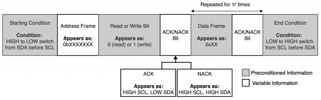
I2C Features
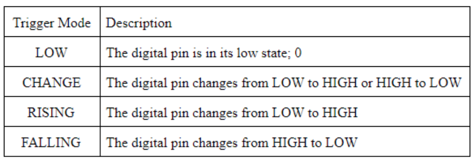
Interrupt service routines (ISR): forces a pre-programmed function to occur given the occurrence of some predetermined event.
The use of ISRs will be reserved for the alert sequence since changes in the pins can easily be linked to the digital signal changes. A summary of predetermined events given by the Arduino Programming Language (APL) that could be recognized by the ARDBOX 20 are shown in the table below.
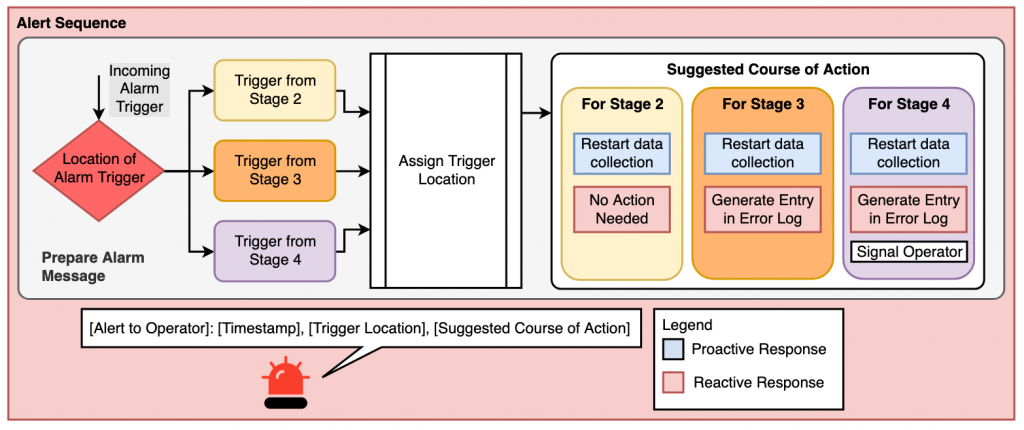
If data is being transmitted and processed correctly, the program will indicate that data is properly read and continue to the next stage. Should the data not be transmitted or processed correctly, an alert sequence will be executed. Throughout the 5 stages, the alert sequence can be triggered from 3 of them; the precheck, screening, and processing.
Codes
Interrupt Service Routine with an LCD and 2 Buttons:

I2C Slave Address Scanner to test standard 7-bit addresses:

Testing Code for Sensors connecting to Analog Pins:
