
Overall System Layout
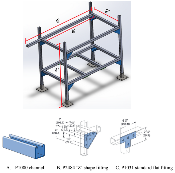
Unistrut was chosen as the structural support material due to its availability, convenience in assembling, and its capability of handling large loads. The fittings shown in the image below will be incorporated onto the P1000 channel to ensure the structural integrity of the unistrut base. P2484 will act as a gusset between intersecting channels and corners and P1031 will act as a connecting fitter for the two channels set on the bottom platform.
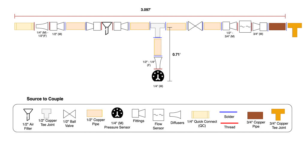
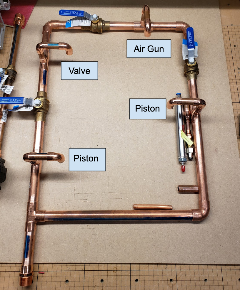
The image provided below showcases the rendering of the distribution loop. Pipe hangers will be mounted throughout the pipe runs and will be suspended from the unistrut support. The dimensions are as follows:
Length: 46.69″ | Width: 15.70 | * Height: 35.23
*From highest to lowest point.

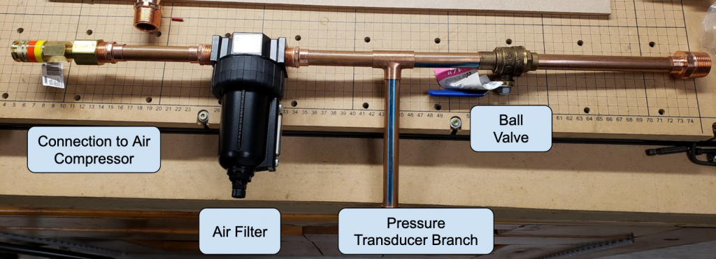
The locations of the pipe supports will be determined by the analysis method for continuous beams. Click here for the full pipe support analysis.
Weight of System
Both the air compressor and air tank are not directly in contact with the test bench, therefore the weight of the components has been excluded from the system’s total weight. The weight of the end user devices such as the pison and air gun have also been relieved from the total weight of the system as they will not be mounted onto the standing plywood, but upon the table top.
| Section | Total Weight (lb) | Excluding Weight (lb) |
| Source to Pipe Distribution | 6.03 | – |
| Loop Distribution | 18.8 | – |
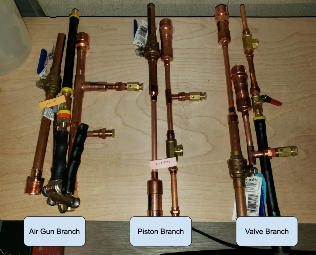
| Piston 1 Branch | 6.53 | Piston Switch |
| Piston 2 Branch | 3.47 | Piston Switch |
| Valve Branch | 4.89 | – |
| Air Gun Branch | 5.77 | Air Gun |
| Total Weight of System | 45.49 | Air Compressor: 105.25 Air Tank: 31 |
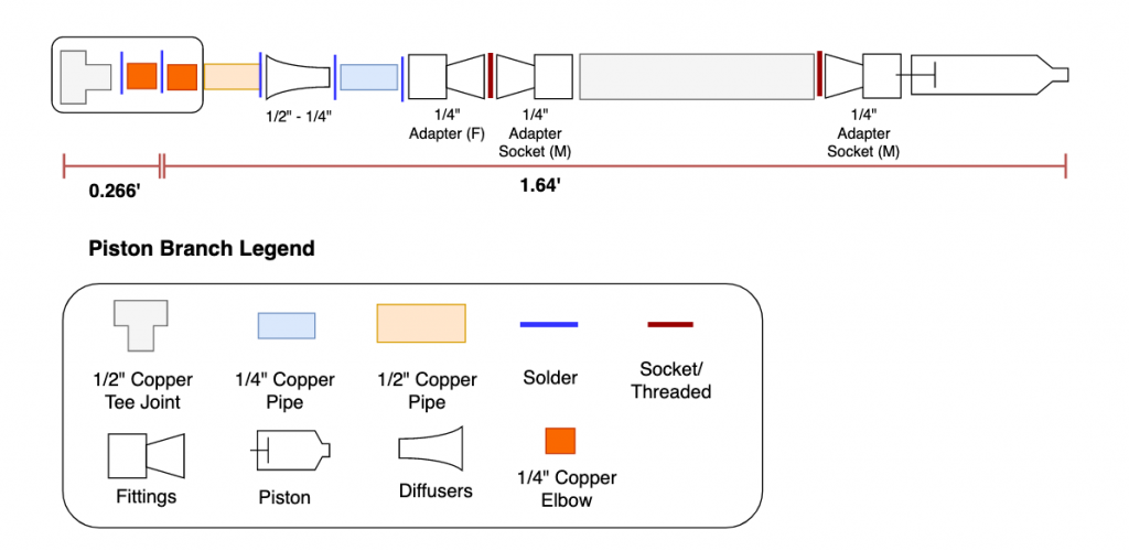
Detailed Piping Layout
Dimensions
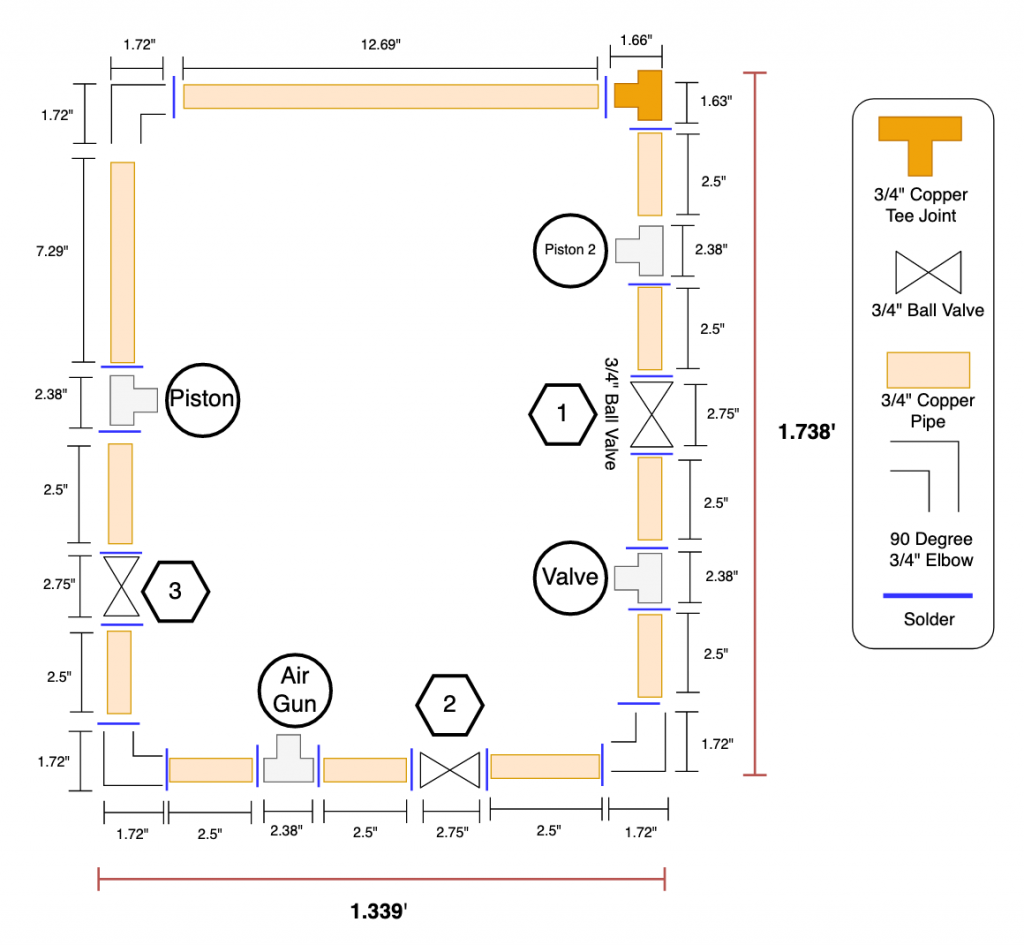
The dimensions of the mechanical piping layout is still currently being specked out; however, a rough estimate of the length per section is provided in the table below. The vertical and horizontal length are determined by the direction of the pipe against the plywood. The direction of the pipes will be displayed in later figures below. A more detailed table of how the lengths of the structure were taken can be found in the piping assembly. The vertical and horizontal lengths depicted for the end user branches do not include the lengths of the devices, as the tools and air hose will not be attached onto the plywood walls, but onto the table.
| Section | Vertical Length (ft) | Horizontal Length (ft) | Total Length (ft) |
| Source to Distribution | 9.71 | 3.0975 | 12.808 |
| Distribution System | 1.74 x 1.34* | 1.74 x 1.34* | 6.155 |
| Piston 1 Branch | 3.44 | 0.53 | 3.97 |
| Piston 2 Branch | ~ 1.72 | 0 | ~1.72 |
| Valve Branch | 3.25 | 0.53 | 3.78 |
| Air Gun Branch | 2.88 | 0.53 | 3.41 |
* not necessarily running ‘vertical’ or ‘horizontal’, but the length and width of the piping loop.
Piping Figures


Click here for pipe assembly.